Insertion loss of VNA testing cables
 2023-02-22
1、What is a network analyzer
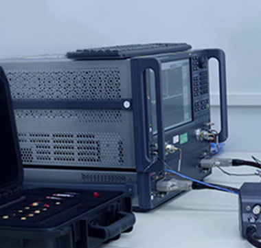
The network analyzer is a new type of instrument for measuring network parameters. It can directly measure the complex scattering parameters of active or passive, reversible or irreversible dual-port and single-port networks, and give the amplitude and phase of each scattering parameter in a frequency sweep mode. frequency characteristics.
2、Classification of network analyzers
2.1. Scalar network analyzer
Only the amplitude information is measured, and the phase measurement is not supported. The receiver adopts diode detection, has no frequency selection characteristics, and has a small dynamic range.
2.2. Vector network analyzer
Measure magnitude and phase information. The receiver adopts tuned reception, has frequency selection characteristics, can effectively suppress interference and spurious, and has a large dynamic range.
3、Test Objects for Network Analyzers
3.1 single port or dual port
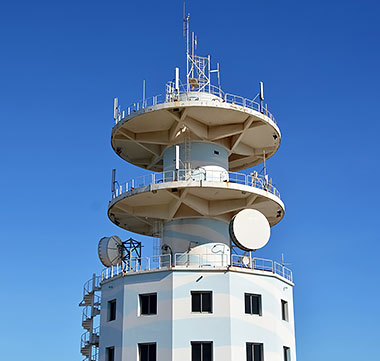
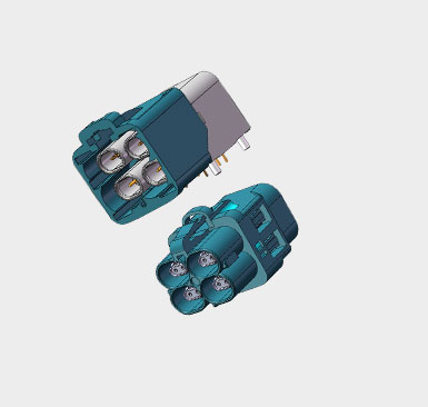
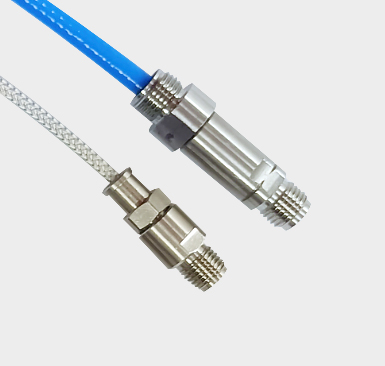
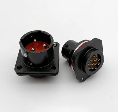
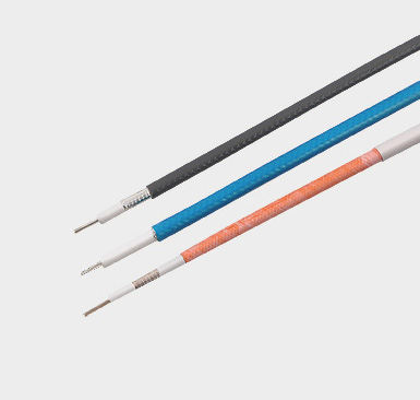
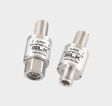
Antennas, matching terminals, filters, attenuators, isolators, amplifiers, connectors, cables
3.2 Multiport
Multiplexers, multiplexers, bridges, directional couplers, power dividers, circulators, transformers, balancing devices
3.3. Frequency conversion devices
Mixers, modulators, conversion frontends
4、The principle of network analyzer
In order to complete the test of the transmission/reflection characteristics of the DUT, the network analyzer includes: an excitation signal source; providing an excitation input signal of the DUT; a signal separation device, including a power divider and a directional coupling device, which extract the input and reflection signals of the DUT respectively
5、Introduction to the main test parameters
The network analyzer can correct the measurement results point by point, and convert dozens of other network parameters, such as input reflection coefficient, output reflection coefficient, voltage standing wave ratio, impedance (or admittance), attenuation (or gain), Transmission parameters such as phase shift and group delay, isolation and orientation, etc. (PS: general companies are mainly used for product transmission, reflection [S11, S12, S12, S22], VSWR testing)
Therefore, when we usually use network analyzers to test R&D or production products, we mainly pay attention to the main factors such as reflection coefficient (return loss), gain/difference loss, isolation/directivity, and group delay of microwave devices. parametric features. No matter which instrumentation supplier provides the network analyzer, it is developed and designed based on this principle and application, but each supplier has different aspects of network analyzer implementation, man-machine interface, frequency coverage, and test speed. There are differences in specific details such as , index level, etc., and other functions are similar, which also depends on the user's habits and approval.
6、How to improve the test accuracy of the network analyzer
Errors in the testing process of network analyzers are mainly divided into three categories: systematic errors, random errors and drift errors..
Systematic errors are caused by imperfections in the instrument's internal test setup. It is predictable and recurring, and generally time invariant, so it can be described quantitatively, and systematic errors can be eliminated by calibration prior to testing. (The part eliminated after calibration with the calibration kit)
Random error is unpredictable because it is random and changes over time, so it cannot be calibrated out. The main source of random error is the internal noise of the instrument, for example, the phase noise of the excitation source, the sampling noise, the background noise of the IF receiver, and the repeatability of the switching action. (It is related to the service life of the screen analyzer and its own quality, which is unpredictable)
Drift error is the drift in test setup performance after meter calibration. Drift errors are mainly due to temperature changes and can be removed by further calibration. The amount of time a meter maintains stable accuracy after calibration depends on how quickly the meter drifts in the measurement environment.
7、Basic classification of calibration
The test of the coaxial structure is mainly calibrated by SOLT calibration parts and electronic calibration parts
8、Feature comparison
8.1. The accuracy of SOLT calibration is better than that of ECal modules;
8.2. SOLT calibration is relatively cumbersome (open, short, load, and through are used for calibration in sequence), and the second electronic calibration part can be directly connected to the network analyzer for one-time calibration;
8.3. The SOLT calibration method is mostly used for laboratory calibration, and the electronic calibration module calibration method is mostly used for production line production.
For different test requirements, sometimes Open, Short, Load, and Through calibration parts do not need to be used at the same time; Need Open, Short, Load or Open, Short and Open to achieve the purpose of calibration (network itself has a matching system algorithm according to different calibration conditions, in addition, we can also connect a computer to design a specific algorithm to achieve calibration ).